Gower & Lee
Dellorto Carburettors
Checking the Mixture on S.U Carburettors
A. Check for correct mixture by gently pushing the lifting pin up about 1/32 in. ( .8mm )
B. The graph illustrates the effect on engine r.p.m when the lifting pin raises the piston, indicating the mixture strength.
RICH MIXTURE:- r.p.m increase considerably.
CORRECT MIXTURE:- r.p.m increase very slightly
WEAK MIXTURE:- r.p.m immediately decrease
If you have any problems with setting the float levels, check all parts for wear and replace where necessary.
H & HD Type (T1 & T2)
The correct way to set the float level is to hold the float chamber lid inverted with needle valve held in the shut-off position by the float arm only .In this position a 7/16" rod or drill bit should be able to be slide between the float arm and the top of the lid.
HS Type (Brass float)
For HS type carburettor's with brass floats carry out the same procedure as above but us a 5/16" diameter rod to check the gap between the float and the lid.
HS Type (Plastic float)
Hold the float lid assembly in the inverted position and measure the gap between the float and the lid. For the early type of plastic float with a metal lever arm the gap should be between 0.125" and 0.187". Small adjustments can be made by bending the metal lever arms. For later all plastic floats the clearance should be between 0.062" and 0.187" but this type is not adjustable.
 .............................................
Early metal lever arm .................................................... Later all plastic float
HIF Type
Hold the carburettor in an inverted position so that the needle valve is held in the shut position by the weight of the float. Check that the point indicated on the float is 1mm +/-0.5mm below the level of the float chamber face.To adjust the float level bend the brass arm which rest on the needle valve. Recheck level and check for free movement of the float.
 If
a persistent slow leakage is observed at the base of the jet unit ( a mere
surface dampness can be generally be disregarded ) it is probable that the
sealing glands and large sealing cork require replacement. The jet lever
or cap should first be detached from the jet head , the locking screw
removed, then the entire jet unit can be withdrawn. All cork seals should
be soaked in oil to prevent splitting on refittment. After the jet
assembly has been refitted it must be correctly centred on the tapered
needle to prevent the piston from sicking during operation.
If
a persistent slow leakage is observed at the base of the jet unit ( a mere
surface dampness can be generally be disregarded ) it is probable that the
sealing glands and large sealing cork require replacement. The jet lever
or cap should first be detached from the jet head , the locking screw
removed, then the entire jet unit can be withdrawn. All cork seals should
be soaked in oil to prevent splitting on refittment. After the jet
assembly has been refitted it must be correctly centred on the tapered
needle to prevent the piston from sicking during operation.
Jet Centering
When the suction piston is lifted by hand (engine not running ) it should fall freely and hit the " jet bridge " with a soft metallic click - that is, with the jet adjusting nut in its topmost position. If this click is not audible, but is so when the test is repeated with the jet in the fully lowered position , then the jet unit requires recentering on the needle.
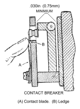 The blade should rest against the projection on the bakelite moulding when
the points are open. The points should make contact when the rocker is mid
position. the tension of the blade must not hinder the rocker action. To
check the gap 0.030in . hold the blade against the moulding and insert a
feeler gauge between pump body and rollers of outer rocker U.
The blade should rest against the projection on the bakelite moulding when
the points are open. The points should make contact when the rocker is mid
position. the tension of the blade must not hinder the rocker action. To
check the gap 0.030in . hold the blade against the moulding and insert a
feeler gauge between pump body and rollers of outer rocker U.
Use a sychrometer if availble to confirm that the carburettors are
balanced by volume. Slight adjustment to balance screw (4) can be made if
necessary.
A vacuum reading from each choke tube can be obtained by removing the
blanking screws (8). Connections can then be made to a suitable manometer
or mercury columns for carburettor synchronisation.
This procedure may also be used on Weber DCOE carburettors
Weber Tuning manual available £14.95
+ p&p
It covers operation principles, adjustment settings, installation checks,
special application, auxiliary components, exploded diagrams & part
numbers for weber performance carburettors.
e-mail :sales@gowerandlee.co.uk
Tel/Fax: +44 (0)1923 247300
Rebuild - Home - Spares - Pumps - Facet - Injector - Powerplus